MX-PDK (5G / O-RAN)
This section is dedicated to the MX-PDK part of the UI. Here you can design networks in the Intent Builder, watch them in Networks and Topology, register and test Terminals, and manage O-RAN apps.
- Networks —
/networks - Intent Builder —
/builder - Terminals —
/terminals - Topology —
/topology/{name} - O-RAN —
/oran,/xapps,/rapps
Networks
Route: /networks
The live control plane of every deployed 5G network. Stat cards at the top count Networks, Cores, Accesses and overall Networks Health. The Build Intent button opens the Intent Builder.
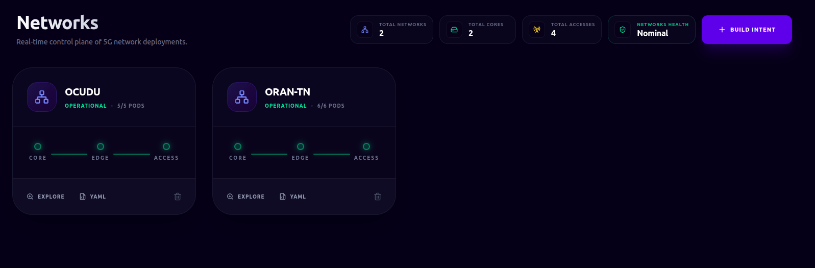
Network card
Each deployed network is a card showing its name, a status pill with pod readiness
(e.g. 3/4 Pods), and a small architecture diagram (Core → Edge → Access) whose connecting
lines are colour-coded by health.
Card actions:
- Explore — open the network in Topology.
- YAML — view the full Kubernetes manifest in a modal.
- Delete — remove the network after a confirmation dialog.
Intent Builder
Route: /builder
The Intent Builder provides a guided, step-by-step visual editor to design, configure, and deploy custom 5G networks. Here you can build end-to-end network topologies — spanning, slices, core networks, Edge/RIC nodes, RAN access nodes, and UEs (Terminals)—before compiling them into deployable network design.
We recommend configuring the tabs in sequential order from top to bottom:
- Adding Components: Each configuration tab features a color-coded Add button (e.g., Add Slice, Add Core, Add Terminal) to instantiate a new component card.
- Removing Components: Active component cards display a trash-bin Delete control to discard the configuration.
- Software Stack Selection: Configuring individual network elements requires selecting a software stack and model (such as OAI, srsRAN, or BubbleRAN) provided by the installed composition models (refer to Models & Operators for details on model management).
1. Global Settings ●
Network identity. Set the network name (which must be unique in the namespace).
Optionally enable Override DNS to provide custom IPv4 resolvers (defaults to 8.8.8.8 and 8.8.4.4).
2. Slices ●
Configure one or more network slices by clicking Add Slice in the Slices tab. The following fields are configurable:
- PLMN Identity (Public Land Mobile Network identifier, e.g.
00101), - Data Network Name (DNN, e.g.
internet), - Network Mode (IPv4, IPv6, or Dual Stack configuration),
- Service Type (SST, such as eMBB, URLLC, or MIoT),
- Differentiator (SD, hex differentiator parameter),
- Layer 3 Address Space (IPv4 and IPv6 subnet ranges, conditionally displayed based on the selected Network Mode)
3. Core Networks ●
Configure one or more core networks by clicking Add Core in the Core Networks tab. The following fields are configurable:
- Core Name (unique name within the same network),
- Stack Model (selectable model from the available composition models),
- Stack Format (selected model, e.g.
5G-SA), - Network Identity (Region ID, CN Group ID, and CN ID),
- Operational Profiles (toggle to enable global debug logging),
- Node Allocation (optional Affinity Pinning to lock the core to a targeted compute node)
4. Edge / RIC ●
Configure one or more Near-RT RICs by clicking Add Edge in the Edge / RIC tab. The following fields are configurable:
- Controller Name (unique name within the same network),
- Controller Model (selectable model from the available composition models),
- Stack Format (selected controller model, e.g.
5G-SA), - Node Allocation (optional Affinity Pinning to lock the RIC to a targeted compute node).
To deploy xApps for a RIC, you can click on the relative Add xApp button and configure the following:
- xApp Name (unique name within the same network),
- xApp Model (selectable model from the available composition models),
- Profiles (selectable profiles from the available models),
- Extra Annotations (optional annotations to further configure the xApp).
xApps configured at this stage are provisioned as part of the initial network deployment. Because their lifecycle is bound to the network infrastructure itself, they differ from Dynamic xApps, which are managed independently after the network is deployed (see O-RAN/xApps).
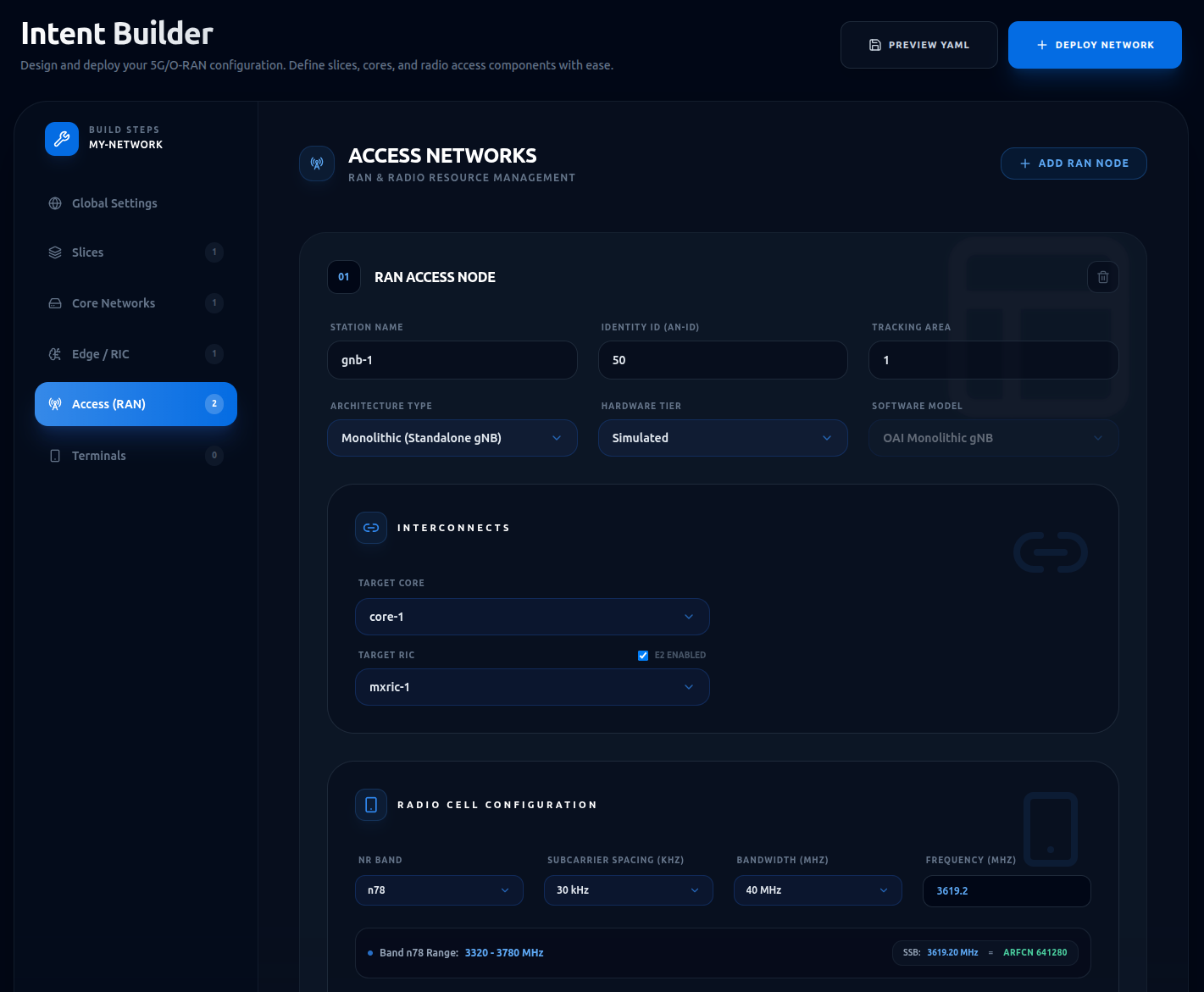
5. Access (RAN) ●
Configure one or more radio access network nodes by clicking Add RAN Node in the Access (RAN) tab. The following fields are configurable:
- Station Name (unique name within the same network),
- Identity ID (AN-ID) and Tracking Area,
- Architecture Type (Monolithic, CU-DU split, DU-only, or External),
- Hardware Tier (Simulated, SDR-Based, or Commercial),
- Software Model (selectable model from the available composition models),
- Hardware Selection (allocated physical resource RU/SDR, hardware model, antenna formation, and optional remote reboot),
- Interconnects (Target Core, optional Target CU, and Target RIC with E2 enabling),
- Radio Cell Configuration (frequency band, subcarrier spacing SCS, bandwidth, ARFCN/frequency, and TDD slots configuration),
- Node Allocation (optional Affinity Pinning to lock the station to a targeted compute node; note that physical hardware mapping enforces a hardware node lock)
Selecting a physical resource will automatically pin the workload to the machine the hardware is attached to.
6. Terminals ●
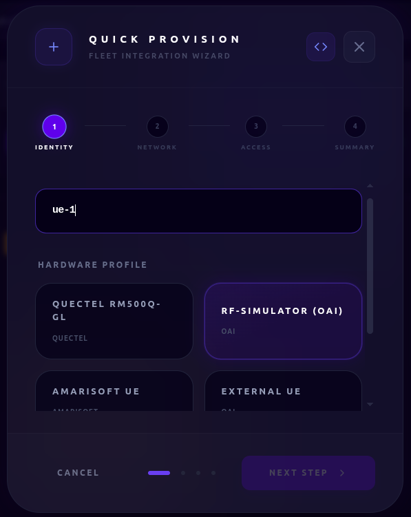
Configure one or more user equipment by clicking Add Terminal in the Terminals tab. The following fields are configurable:
- Terminal Name (unique name within the same network),
- Hardware Profile (e.g., simulated, quectel, external),
- Terminal Model (selectable model from the available composition models),
- Allocated Physical Resource (e.g., Quectel) (depends on selected hardware profile; select the hardware from the available ones),
- SIM Credentials (Subscriber IMSI, Authentication Key K, OP/OPc Parameter, SQN, and USIM PIN),
- Subscribed Data Slice (DNN) (target data slice selection),
- Core Association (associated core network configuration),
- Preferred Cell Access (automated band synchronization mapping with the access node),
- Radio Bands (manual frequency bands configuration),
- Node Allocation (optional Affinity Pinning to lock the terminal compute container to a targeted node)
This step performs both the registration in the network core database and when applicable the configuration of the physical or simulated UE hardware. Terminals can be provisioned either during the initial network design phase (alongside the core and access infrastructure) or dynamically at runtime via the dedicated Terminals management page (see Terminals).
Preview & Deploy
- Preview YAML: Opens a modal showing the generated Kubernetes manifests (slices, cores, etc.).
- Deploy Network: Validates and deploys the configuration to the cluster. Any validation errors (e.g., name conflicts or missing components) are displayed in an error banner.
Terminals
Route: /terminals
The Terminals page is your central hub for managing the lifecycle of User Equipment (UEs) across your cluster. It provides a unified interface to register new hardware, monitor the attachment state of your fleet, and perform deep-dive diagnostics on active connections. This list includes UEs both configured during initial deployment (Intent Builder) or dynamically at runtime (Quick Provision).
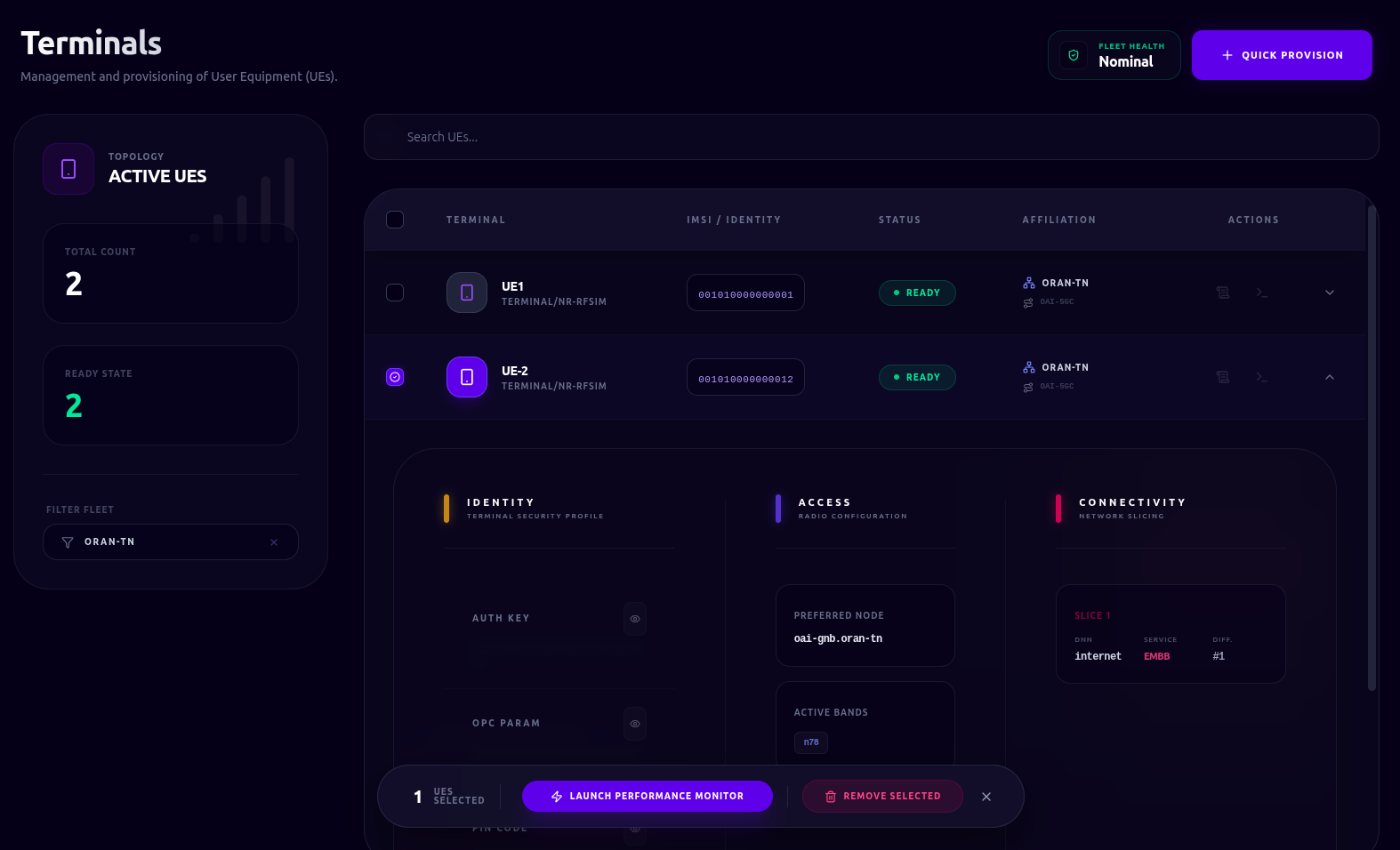
The Left Panel provides at-a-glance telemetry of your Active UEs and Ready counts. You can use the Filter Fleet dropdown to scope the view to a specific network or view your entire multi-network deployment simultaneously. In the UE Table, you can quickly identify devices by their Terminal Name, Model, and IMSI. The Status column uses consistent color-coding to help you spot attachment issues immediately:
| Colour | Status | Meaning |
|---|---|---|
| 🟢 | Ready | Device is successfully attached to the network. |
| 🔵 | Attaching | The attachment procedure is currently in progress. |
| 🔴 | Failed | The device failed to attach; check logs for detailed error messages. |
Expand a row to reveal a three-column detailed panel:
- Identity — Auth Key, OPC, PIN, SQN (each maskable with an eye toggle).
- Connected Cores & Slices — active connections and slice affiliations.
- Access Info — Frequency band and preferred access node (if configured).
Every terminal provides direct access to the underlying container infrastructure:
- Live Logs: Stream real-time signaling and application logs from the attachment pod to diagnose protocol-level issues.
- Shell Access: When a terminal is in a Ready state, you can open an interactive terminal session directly into the pod for manual configuration or troubleshooting.
Quick Provisioning
To add a new device to a network at runtime, use the Quick Provision modal. This guided workflow handles:
- Hardware Profiling: Selecting a device profile (e.g., Quectel module) to automatically map supported frequency bands and available hardware.
- Subscriber Identity: Configuring the IMSI and USIM credentials with live validation.
- Network Mapping: Associating the terminal with a target network and synchronizing radio parameters directly from the active gNodeB.
Performance Monitor
Terminals performance can be monitored in real-time by selecting one or more terminals across one or more networks and launching the Performance Overlay:
- Throughput Benchmarking: Measure real-time DL/UL bandwidth using area charts.
- Latency Testing (RTT): Track round-trip time stability via line charts.
Tests can be triggered per-UE or in batch and with separate durations. Results are plotted in real-time to help you identify bottlenecks or interference patterns.
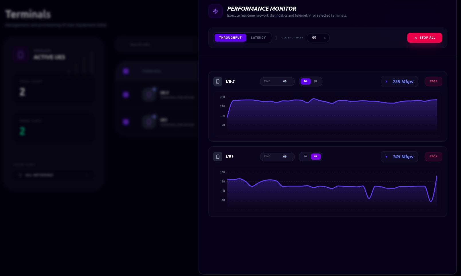
These tests cannot be performed on terminals that are not managed by the cluster (e.g., external) or if they are not ready.
Topology
Route: /topology/{networkName}
The Topology view provides an interactive, real-time visualization of your network's architecture. Rendered as a live graph, it allows you to observe how components are interconnected and how their operational state evolves as the cluster reconciles your intent. Network topology can be accessed by clicking the Explore button for the selected network in the Networks section.
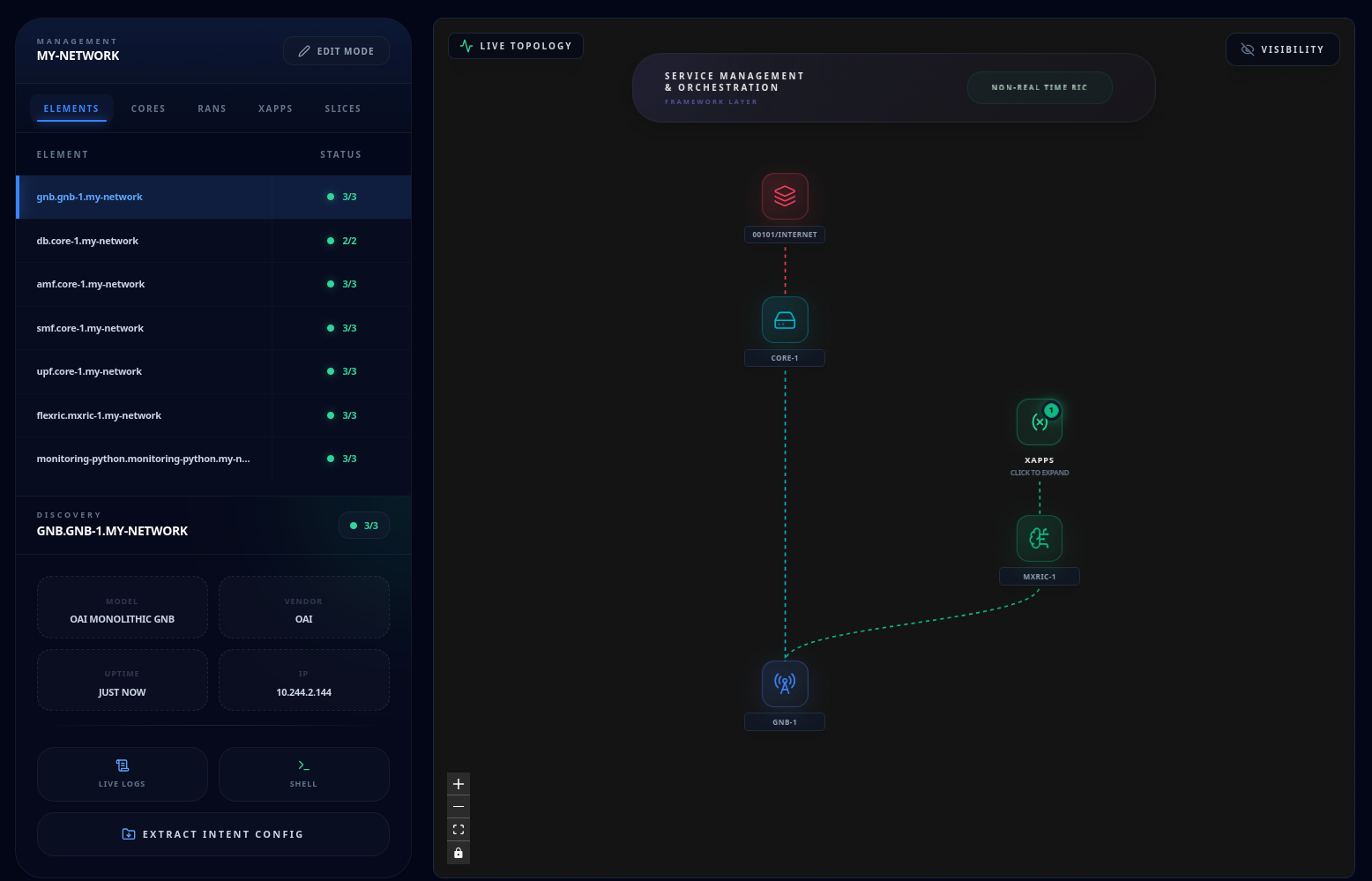
Visualizing the Architecture
The graph maps the entire end-to-end path—from the Core and Edge layers down to individual RAN nodes and attached Terminals. Each node is color-coded by its functional type, and animated edges represent the logical and physical signaling paths between them.
| Colour | Node | Description |
|---|---|---|
| 🔴 | Slice | Logical network slices (PLMN/DNN). |
| 🔵 | Core | 5G/LTE Core network functions. |
| 🟢 | RIC / Edge | Near-Real-Time RAN Intelligent Controllers. |
| 🟢/🟣 | xApp / rApp | O-RAN applications; a DYN badge indicates runtime-attached dynamic apps. |
| 🔵 | Access (RAN) | Radio access nodes (gNodeB/eNodeB). |
| 🟡 | Terminal | User Equipment (UE). |
Nodes feature a status aura that reflects their current Kubernetes readiness:
- Solid Green: The component is healthy and fully operational.
- Pulsing Amber: The component is currently deploying or reconciling.
- Solid Rose: The component has encountered an error; check logs for details.
Use standard navigation controls to pan, zoom, and fit the view. To keep the visualization clean in high-density deployments, use the Visibility Toggles to show or hide optional layers like Terminals or rApps. For complex RIC deployments, you can expand or collapse xApp/rApp clusters by clicking the associated group badge.
On the left side, the relative pods and their status will be shown. Pods can be filtered per type from the top left bar.
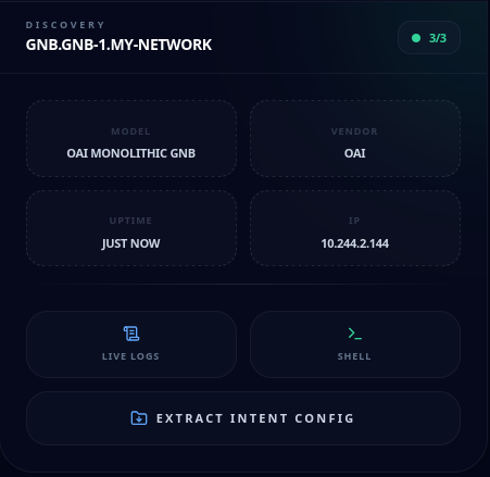
Element Deep-Dive
Selecting any node in the graph (or a row in the filtered pods table) opens the Element Detail Panel on the right. This panel provides a "one-stop" view for component-level diagnostics:
- Specifications Grid: View live metadata including Model, Vendor, Uptime, and internal IP addresses.
- Integrated Diagnostics: Launch Live Logs or an interactive Shell directly from the node context.
- Intent Extraction: Use the Extract Intent Config button to download a comprehensive archive of the pod's configuration files for offline audit or debugging.
Live Editing
Topology view also supports live editing. Network deployment can be changed at runtime by clicking the button Live Edit on the top left bar.
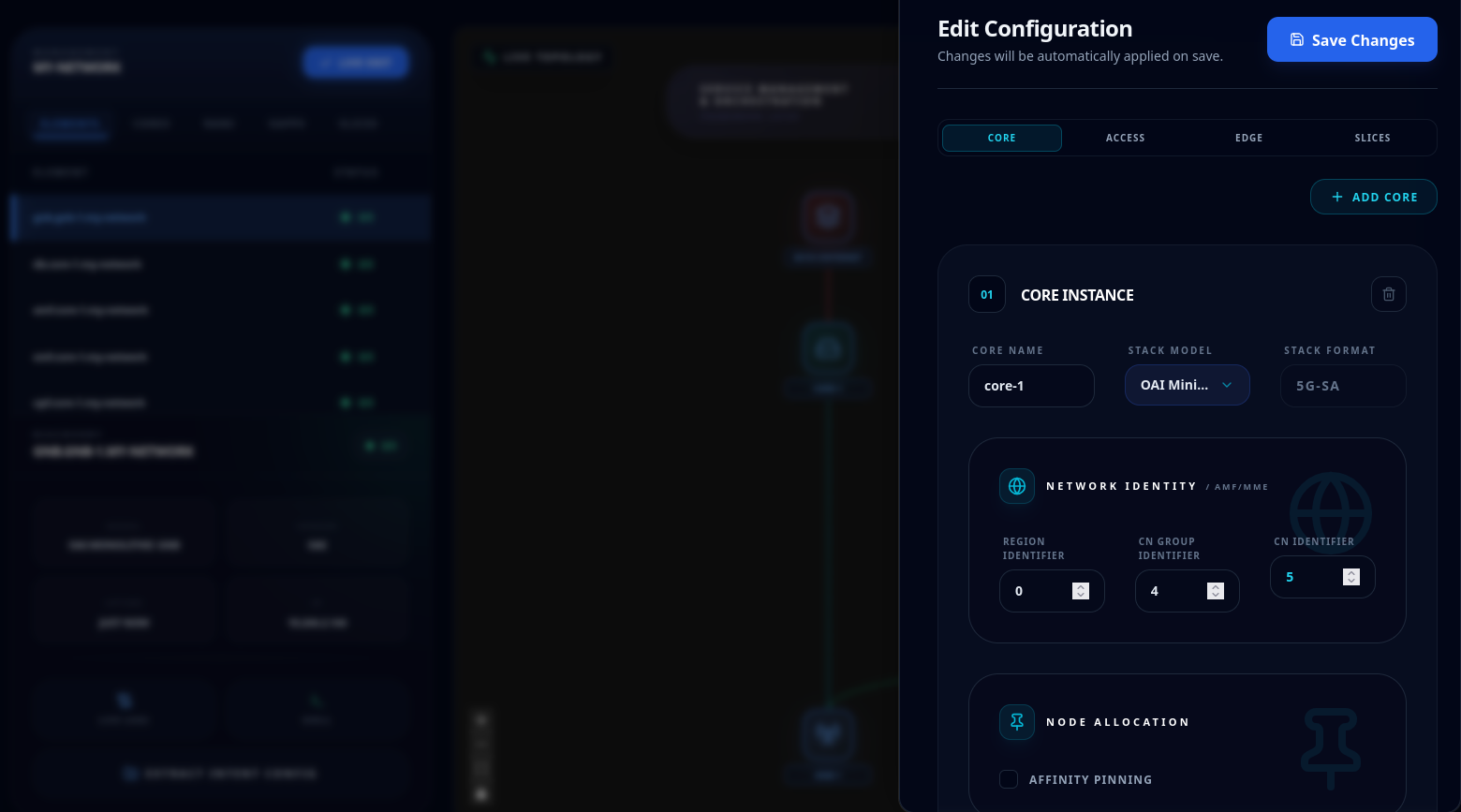
Once clicked, each network component will be glowing blue. Select the component that you would like to edit, and a side bar will be shown.
The panel mimics the same structure of the Intent Builder. You can therefore add, delete or change the configuration of the components in the deployed network.
Live editing does not yet support runtime migration of hardware type in the access components. Any component can be edited, besides the xApps and the rApps marker with a DYN badge. Those are handled in the O-RAN section.
O-RAN
Route: /oran
The O-RAN section is the runtime management hub for Dynamic xApps and Dynamic rApps — O-RAN applications that are deployed and removed independently of the network lifecycle. This is distinct from static xApps provisioned during initial network design in the Intent Builder.
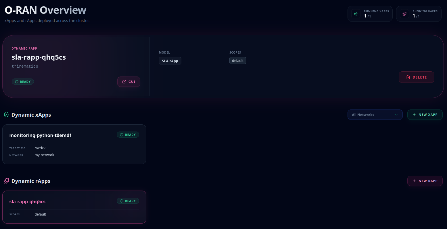
The page header displays live aggregate counts: Running xApps and Running rApps. A network filter scopes the xApp view to a single network, while rApps are applied at the cluster level. Below the stats, two card grids list all deployed instances. New xApp and New rApp action links navigate directly to the respective builders. Selecting any card opens a detail panel showing its current status and a Delete action.
xApps
Route: /xapps
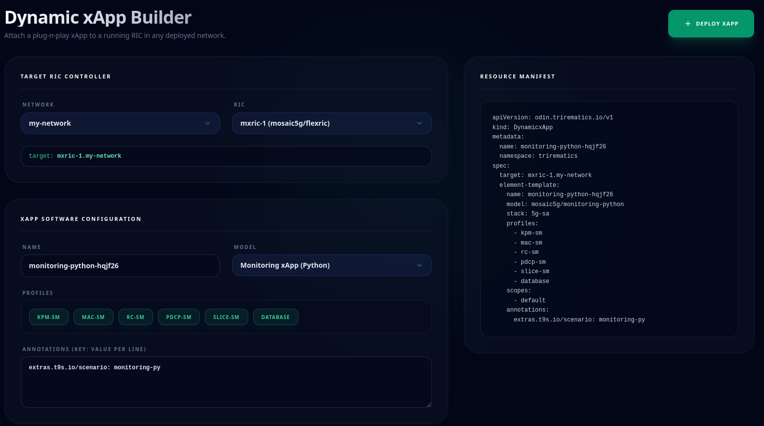
The Dynamic xApp Builder deploys a DynamicxApp onto a running Near-RT RIC. The form is split into two sections:
- Target RIC — select a Network, then pick a RIC from that network.
- xApp Software — provide a Name (auto-generated, editable, and uniqueness-validated), choose a Model, and optionally toggle Profiles and other model dependent options.
The Resource Manifest panel on the right updates in real time as you edit the form. Deploy xApp validates the configuration and deploys the xApp.
rApps
Route: /rapps
The Dynamic rApp Builder deploys a DynamicrApp onto the Non-RT RIC.
As for xApps, select a Model and provide a Name; a live manifest preview reflects your inputs. Deploy rApp validates and submits the request.
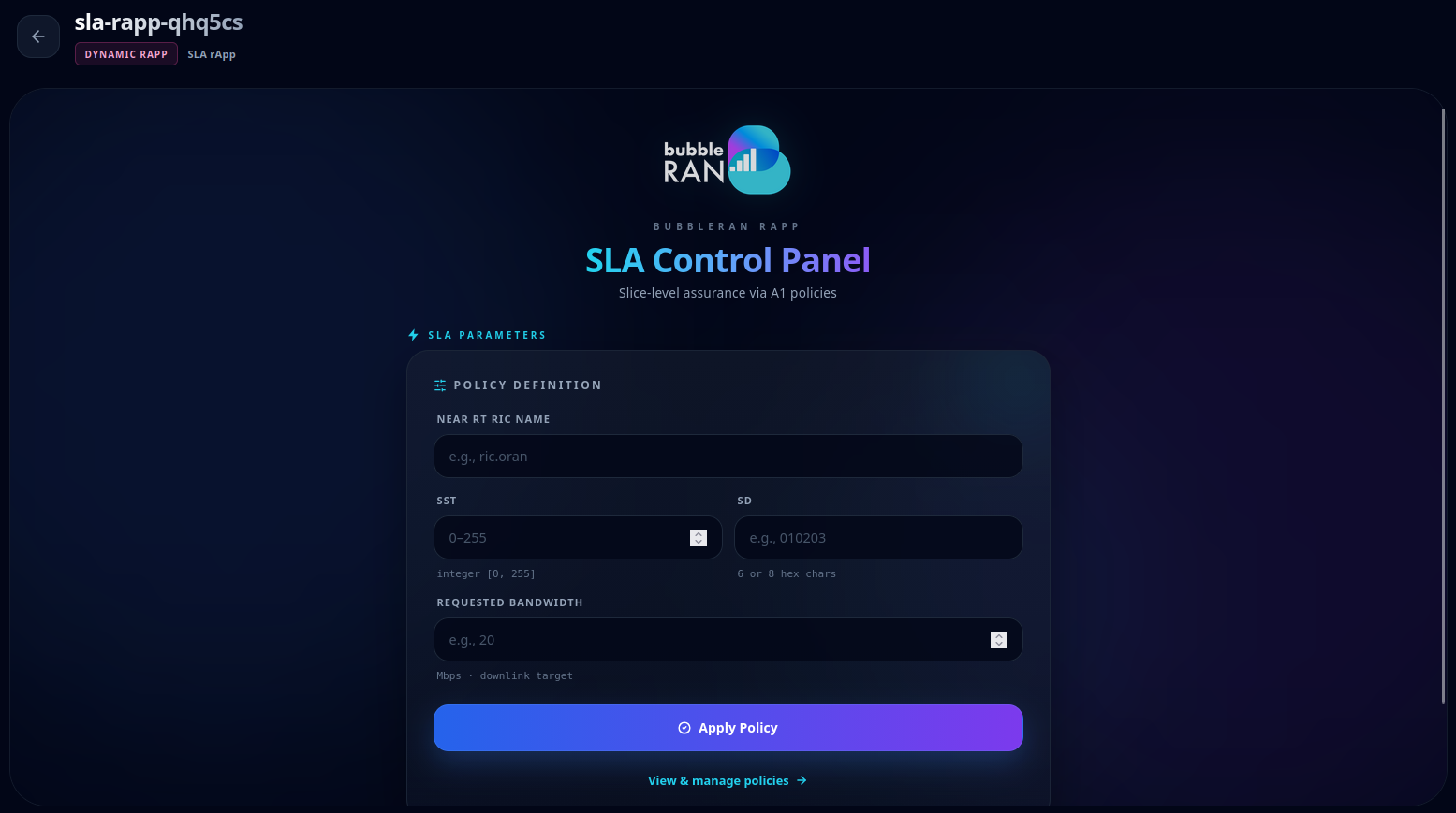
A deployed rApp that ships its own UI can be opened full-screen inside the console via an embedded frame, accessible from the O-RAN Overview section by clicking the GUI button.
For example, the image shows the GUI for the integrated SLA rApp.