5G FR2 with Trirematics
| Title | 5G Frequency Range 2 (FR2) Deployments with Trirematics |
| Venue | Eurecom |
| Dates | November 2022 |
| Location | Biot, France |
Synopsis
In this demo, we presented BubbleRAN's FR2 solution using Amarisoft FR2 stack. The demonstration involves both using Snap packages and on Kubernetes.
Use Cases
- Ultra High Data Rates (+600 Mbps in Downlink)
- Millimeter Wave (mmWave) Spectrum
Contact us for a private demo or to receive the media on this specific demo.
Introduction
This guide describes how to set up and run a 5G-NSA FR2 network using Amarisoft software embedded in Trirematics Snaps and Amarisoft provided hardware. At then end you find the deployment file for the Kubernetes case, but the hardware setup is the same. This guide is describing how to run 5G-NSA with a 2x2 MIMO eNB and a 1x2 SIMO FR2 gNB.
In order to operate the network, you should obtain from Amarisoft the required hardware and license for at
least the release 2022-09-16 of their software.
Finding a UE that supports FR2 may not be a straightforward task. We recommend using the Samsung Galaxy S20+ 5G SM-G986U1 (beware the model number should be SM-G986U1). beware that in case you buy a second hand phone that it should be unlocked. See the About the UE section for more details.
Hardware setup
Hardware list
The required hardware for setting up a FR2 base station is:
- An x86 server with at least one PCIe x8 slot wired as x8. We recommend the intel i9-10920X processor on an Asrock Rack X299 WS/IMPI motherboard. Asrock Rack can provide such a machine assembled and ready to use.
- An Amarisoft SDR100 software defined radio provided by Amarisoft.
- A GNSS disciplined oscillator with a 10MHz output and its power supply.
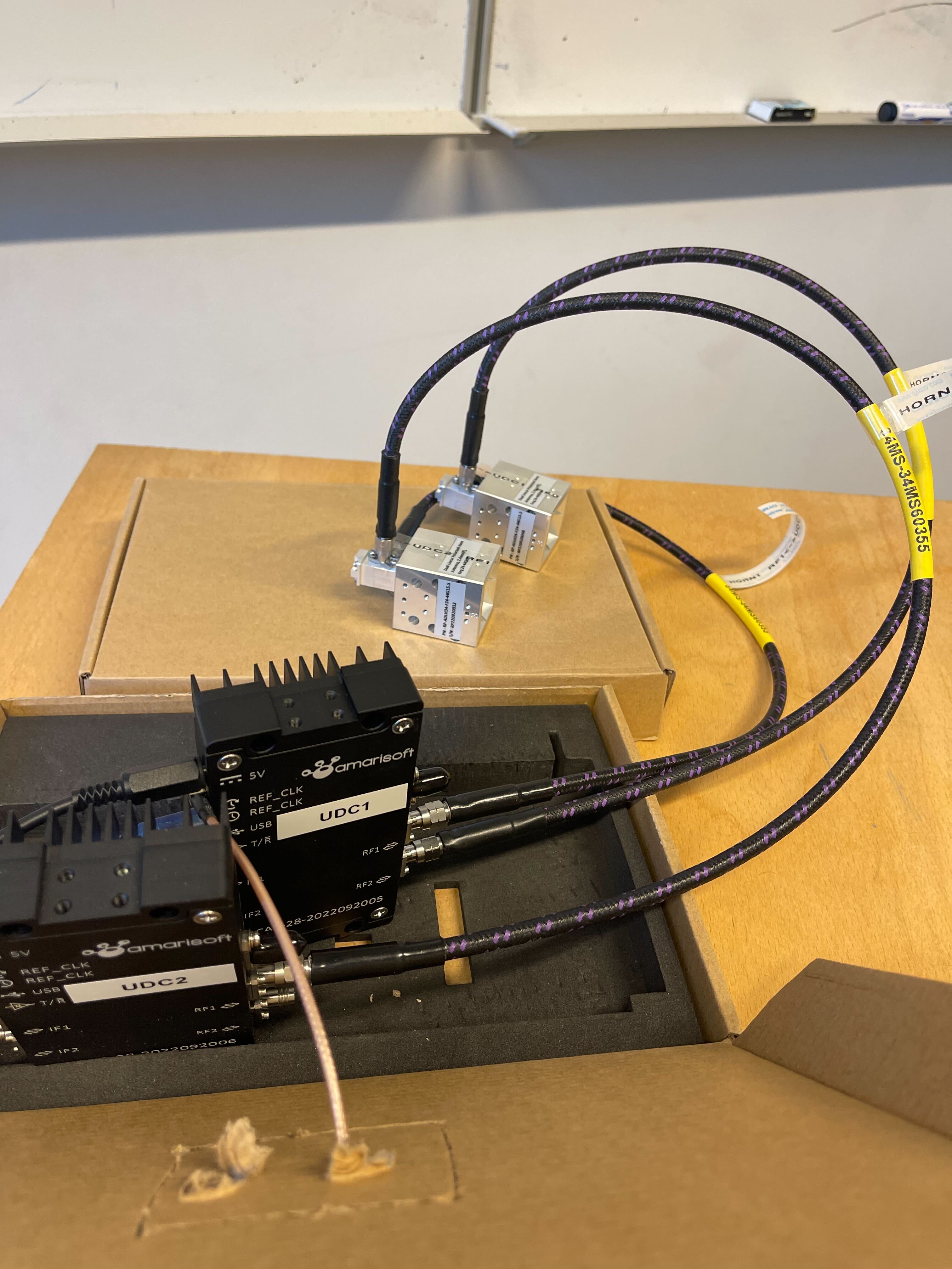
- Two up down converters (UDC) provided by Amarisoft with their power supplies.
- Two mini USB to USB cables.
- Three FR2 coaxial cables.
- Two polarized horn FR2 antennas provided by Amarisoft.
- A GNSS antenna with the plug type corresponding to your oscillator.
- Four FR1 antennas.
- Few coaxial cables and adapters depending on which exact hardware you found.
Assembly instructions
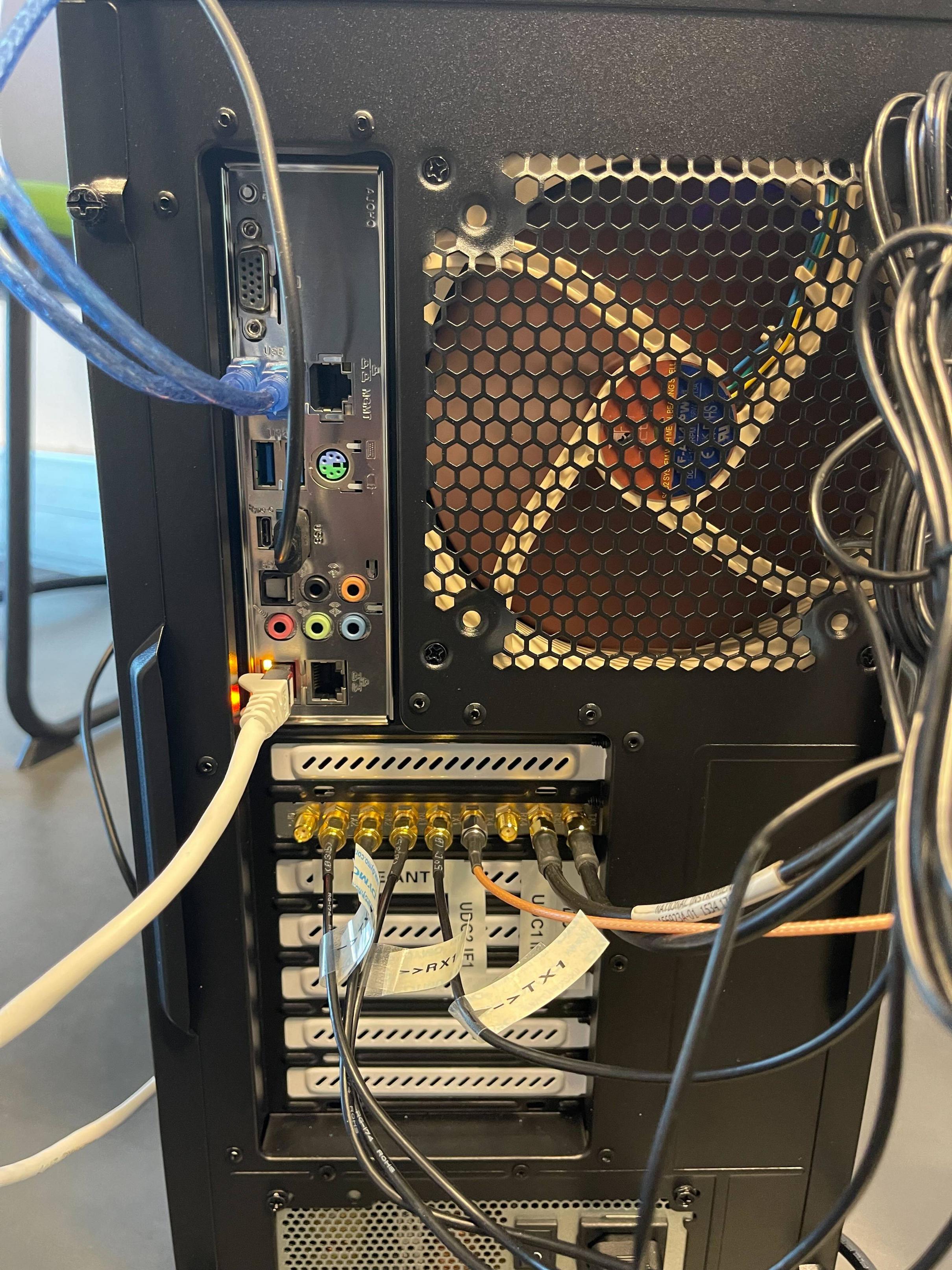
- On the Asrock Rack X299 WS/IMPI motherboard, add the Amarisoft SDR100 on any PCIe slot. No system settings are required, the automatic bifurcation of PCIe works fine. If you are having a card on a PCIe x16 slot on the same motherboard, note that putting the SDR on an adjacent x8 slot would automatically reduce the width of the x16 port to x8. Please refer to the motherboard manual for more precision.
- Connect the four FR1 antennas to ports TX2, RX2, RX1 and TX1 on the frontend of the SDR100 (Fig2).
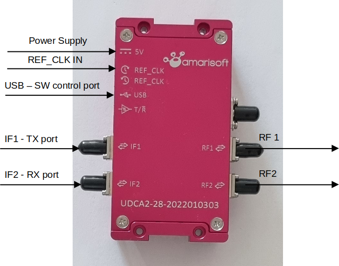
- Using FR2 coaxial cables, connect the UDCs to the SDR100 (Fig1):
- Connect IF1 of UDC1 to TX3 of SDR100
- Connect IF2 of UDC1 to RX3 of SDR100
- Connect IF1 of UDC2 to TX4 of SDR100
- Connect the mini USB ports of both USB to the server using the two mini USB to USB cables.
- Connect the power supply of the UDCs.
- Add the GNSS oscillator:
- Connect the 10MHz output of the oscillator to the upper
REF_CLKport of both UDCs (the one with a clockwise turning clock symbol). Use a coaxial T splitter and adapted coaxial cables. - Connect the GNSS antenna to the oscillator and place the antenna in sight of the sky.
- Connect the power supply of the oscillator. Depending on your model, it may be a simple USB plug that you can connect to the server.
- Connect the 10MHz output of the oscillator to the upper
- Connect the FR2 horn antennas to the UDCs (Fig3):
- Connect RF1 of UDC1 to first port of antenna 1.
- Connect RF2 of UDC1 to first port of antenna 2.
- Connect RF1 of UDC2 to second port of antenna 1.
UDC initialization script
You should get the script named UDC_new.sh.
Then you should run it 3 or 4 times to make sure it works well with the following options for the first UDC:
./UDC_new.sh -M 2 -L 24000 -S /dev/ttyACM0
And then again 3 or 4 times with the following options for the second UDC:
./UDC_new.sh -M 2 -L 24000 -S /dev/ttyACM1
Using Snaps
Snap Installation
The following snaps are required to be installed on the machine:
amr-cnat least version v3.4.0-2022.09.16amr-ranat least version v3.4.0-2022.09.16amr-utilsat least version v3.4.0-2022.09.16
Follow the following instruction to install each snap:
- Install the snap
- Run the
infocommand of the snap in order to get a list of required plugs:sudo <snap-name>.info - Connect all the required plugs with the command:
sudo snap connect <snap-name>:<plug-name> - After all the plugs are connected, the command
sudo <snap-name>.infoshould output:Ddd, DD Mmm YYY HH:MM:SS +0100: [SUC] All the plugs are connected.
Amarisoft License
This guide describes how to use static demo licenses.
For other types of license, please refer to Amarisoft instructions.
This guide will indicate where the license files or license related file should be located for use with the snap
(i.e., where the files located under /root/.amarisoft/ in bare metal Amarisoft should be located for using the
snaps).
Amarisoft provides two licenses files:
ltemme.keyfor the core networklteenb.keyfor the RAN
If it does not exist yet, first create the directory .amarisoft under /root/snap/amr-cn/current.
Then, ltemme.key should be copied to /root/snap/amr-cn/current/.amarisoft/ltemme.key.
This operation requires to be root.
Beware that /root/snap/amr-cn/current is a symbolic link pointing to the root directory of the latest version of
the snap that was installed.
If you update the snap, this link may change, and you may need therefore to copy the license file again.
The file lteenb.key should be copied to /root/snap/amr-ran/current/.amarisoft/lteenb.key.
This operation requires to be root.
Beware that /root/snap/amr-ran/current is a symbolic link pointing to the root directory of the latest version of
the snap that was installed. If you update the snap, this link may change, and you may need therefore to copy the
license file again.
Using Amarisoft Web GUI
It is a very useful graphical tool from Amarisoft that allow to debug lots of behavior. Use the following command to start the web server:
amr-utils.web-server -d ~/snap/amr-utils/common
Then you can access the GUI in your browser at the address of the web GUI server suffixed by /lte/ and on port 8080.
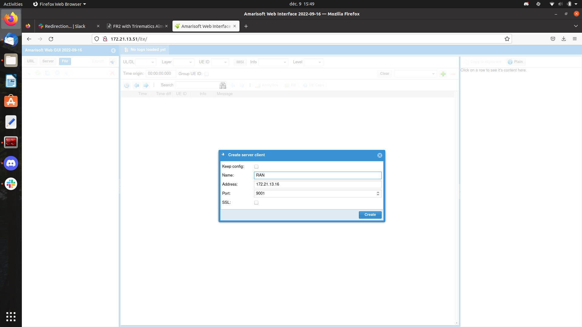
Then you should connect to the Amarisoft CN or RAN.
Click on the Server in the top left corner to display a wizard where you will indicate the name you want to give
to the server, the IP address of the machine that run Amarisoft and a port number which is 9000 for the CN and 9001
for the RAN (The port can be configured at the CN and RAN, the one we provide here are the default configured values).
You can add multiple servers (i.e., CN and RAN) on the same GUI.
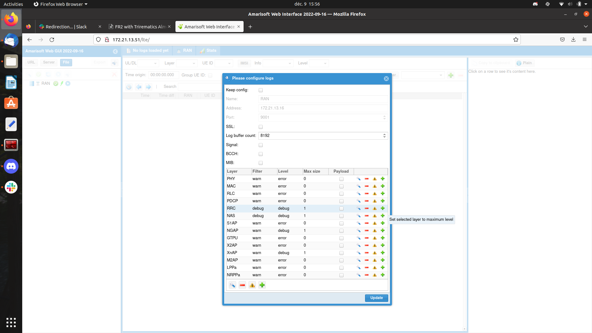
When the server (either CN or RAN) is running and the web GUI connects to it, a layer configuration wizard appears
that allows you to configure the information you want to display.
We recommend for the FR2 setup to set RRC layer to the maximum level by using the green + on the RRC line.
Press update to validate.
Then the RRC messages issued in the network will display.
If you click on a UE capability message the UE Caps button which is on the top of the window will light up.
You can then click on it to display the UE capabilities in a easy-to-read format.
Amarisoft lteview�
Amarisoft lteview is a kind of spectrum viewer that uses the Amarisoft SDR RX radio chain in order to display a spectrum. It is useful for checking that the radio chain works properly, especially the UDCs. Consult BubbleRAN for installation instructions.
Here is how one runs it to perform a loopback test in order to check that the UDCs are working properly:
sudo -E ./lteview config/view-nr-fr2.cfg -D TEST=0 -D CARRIER_FREQ=28000.08 -D IF_FREQ=4000.08
The -E option of sudo is needed to perform X forwarding.
To enable X forwarding you should be running this command through ssh with the -X option.
Using Amarisoft lteview requires to own a RAN license that includes this tool.
A copy of the lteenb.key license file should be placed under /root/.amarisoft/ or under ~/.amarisoft/ if you
are using the -E option of sudo.
In parallel, an instance of the RAN performing a PDSCH test can be run to generate a signal that you can loopback through one UDC to test that this UDC is working. We can provide a configuration file of the RAN to perform this PDSCH test. By looping back the signal through a UDC, we mean the following setup:
- SDR port TX1 is connected to UDC port IF1 with a FR1 cable.
- SDR port RX3 is connected to UDC port IF2 with a FR1 cable.
- UDC ports RF1 and RF2 are connected together with a FR2 cable.
- The UDC is initialized using the
UDC_new.shscript. See the UDC initialization section.
Snap Configuration
Core Network configuration
The amr-cn snap provides a set of command to manipulate the configuration files of the core network.
The active core network configuration file can be edited with the command:
sudo amr-cn.conf-edit-cn
The configuration files available in the amr-cn snap under the directory /var/snap/amr-cn/common/ are listed by
the command:
sudo amr-cn.conf-list
The path of the active core network configuration is displayed by the command:
sudo amr-cn.conf-get-cn
The active core network configuration file can be set with the following command where <file> is either the
absolute path of the file or its name under /var/snap/amr-cn/common/:
sudo amr-cn.conf-set-cn <file>
In most cases, you should try to use the test PLMN 00101 and the test APN internet as they are already configured.
Many UEs will not be able to connect to the network if you use a different PLMN or APN.
UE database
The configuration file of the core network contains a field ue_db which is a list of UEs authentication information.
Each record in this database looks like:
        {
            "sim_algo": "milenage",
            "imsi": "001010000000001",
            "opc": "C42449363BBAD02B66D16BC975D77CC1",
            "amf": 36865,
            "sqn": "ff9bb4000001",
            "K": "fec86ba6eb707ed08905757b1bb44b8f"
        },
You should either add a field with the same IMSI, OPC, SQN and key as the SIM-card you will be using or create a SIM-card with the authentication information of one of the UEs that is already in the database.
PDN and APN
The core network configuration file contains a field named pdn_list which is a list of PDNs described in records like:
        {
            "pdn_type": "ipv4",
            "access_point_name": "internet",
            "first_ip_addr": "12.1.1.2",
            "last_ip_addr": "12.1.1.126",
            "ip_addr_shift": 0,
            "dns_addr": [
                "172.21.3.100",
                "8.8.8.8"
            ],
            "erabs": [
                {
                    "qci": 9,
                    "priority_level": 15,
                    "pre_emption_capability": "shall_not_trigger_pre_emption",
                    "pre_emption_vulnerability": "not_pre_emptable"
                }
            ]
        },
The default configuration file contains three PDN:
- The PDN for internet connectivity which commonly have the APN
internet. - The PDN for IMS which commonly have the APN
ims - The PDN for emergency calls which commonly have the APN
sos. We recommend to do not change this PDN list. Please note down the APNs, they will be required to configure the UEs.
Having an IMS PDN is mandatory for COTS UEs to be able to connect to the network.
Configuration of IMS on the UE changes model to model, but ims as an APN is commonly used.
RAN configuration
PLMN
UE band combination support
As of today, FR2 works only for only in 5g NSA mode. Therefore, the UE will be connected through LTE and NR at the same time on two different band. Not every couple of LTE and NR bands can be used. A UE implements limited set of LTE+NR bands. When the network issues a UE capability enquiry, the uE informs the network if it supports the couple offered by the base station.
The supported couples are presented cleanly in the Amarisoft web GUI when clicking on the UE caps button that is
available when selecting a UE capability RRC message with its payload.
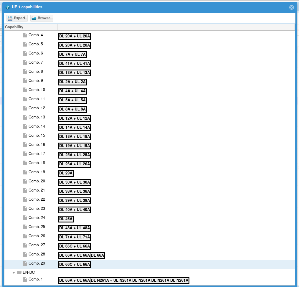
For connecting a Samsung S20+ 5g SM-G986U1 we used LTE band B66 and NR band N261 that is supported by this UE.
Running
Initialization
The following steps should be redone each time the machine is powered on.
You should run the UDC_new script 3 or 4 times with the following options for the first UDC:
./UDC_new.sh -M 2 -L 24000 -S /dev/ttyACM0
And then again 3 or 4 times with the following options for the second UDC:
./UDC_new.sh -M 2 -L 24000 -S /dev/ttyACM1
It is required to run the UDC_new.sh script because some communication behavior can affect the UDCs.
Snaps
Finally, the two snaps need to be initialized with the command <snap-name>.init.
sudo amr-cn.init
sudo amr-ran.init
Core network
- Start the Amarisoft core network either in foreground with the command:
sudo amr-cn
Running the core network in foreground allows to use the core network CLI. This is convenient for debugging purpose. Or in background with the command:
sudo amr-cn.start
- When you are done with the network and all the RAN instances are stopped, you can stop the Amarisoft core network which is running either in foreground by running in the CLI:
> quit
Or in background by running the command:
sudo amr-cn.stop
The CLI offers a bunch of useful commands among which you will find:
helpthat displays a short description of the commands available.enbthat displays the eNBs connected to the core network. Amarisoft RAN when it is used as a NSA eNB+gNB appears as only one eNB.
RAN
We recommend to run the Amarisoft RAN in foreground in order to have access to the RAN CLI. Run:
sudo amr-ran
When you are done with the RAN, stop it by running in the CLI:
> quit
The CLI offers a bunch of useful commands among which you will find:
helpthat displays a short description of the commands available.tthat displays the activity of the UEs connected to the RAN is a very useful tool for debugging.
About the UE
Finding a UE
As of now, there is only one UE that works reliably with this setup: The Samsung Galaxy S20+ 5G SM-G986U1 We insist on that the model number should be SM-G986U1. There are no warranty that any Samsung Galaxy S20+ 5G will be supported. The bands supported by a UE is more related to the market to which the UE is designated than to the series it belongs to.
In case you want to get another FR2 phone, here are few guidelines we provide with no warranty of accuracy. You should anyway check with the model number if the phone supports FR2:
As a best practice to find the specific UE presented above or any other UE that supports FR2 bands, we recommend to target your search on the UEs designated to be used in the USA or Porto Rico. Warning: If you are buying a second-hand phone from the US please make sure that it is unlocked.
According to our research the US Version of Samsung Galaxy S20+, S20 Ultra, S21 FE, S21, S21+, S21 Ultra, S22 and S22+ should work fine.
APN settings
On any UE, you should configure at list one APN to connect to, the internet connectivity APN for which you noted down the name when looking at the core network configuration. When using a cellphone, you should also configure the IMS APN. To add an APN under Android go to the settings the to Network and Internet > Mobile Networks > APN(in the advanced options). Here you can add an APN with the + on top of the menu. You should give the name you want to the option, give the APN name you found in the configurations in the APN field and finally set the APN type to internet for the internet APN and ims for the IMS APN. Finally, use the 3 dots on top of the wizard and the save to save this option.
On Kubernetes
You could use this sample deployment to run FR2 on Kubernetes.
apiVersion: core.trirematics.io/v1
kind: Network
metadata:
    name: amr-fr2
    namespace: trirematics
    annotations:
        trirematics.io/license: Commercial
        trirematics.io/provider: BubbleRAN
spec:
    slices:
        -   plmn: "00101"
            dnn: "internet"
            network-mode: "IPv4"
            service-type: eMBB
            differentiator: "0x000000"
            ipv4-range: "12.1.1.0/24"
            ipv6-range: "2001:1:2::/64"
    access:
        -   name: amr-ran
            vendor: amr
            stack: 5g-nsa
            model: amr-simple-ran
            deployment-mode: demo-ran
            annotations:
                extras.trirematics.io/ue-measurements: "inactive"
                extras.trirematics.io/verbose: "false"
                extras.trirematics.io/pcap: "false"
                extras.trirematics.io/udc-config: "false"
            identity:
                an-id: 1
                tracking-area: 1
            radio:
                device: amr-sdr100
                antenna:
                    tx-gain: "60.0"
                    rx-gain: "45.0"
                    formation: 2x1
            core-networks:
                - amr-cn.amr-fr2
            cells:
                -   band: b66
                    arfcn: 66886
                    bandwidth: 20MHz
                    subcarrier-spacing: 15kHz
                    groups:
                        -   kind: nsa
                            name: nsa-group
                            main: true
                -   band: n261
                    arfcn: 2079167
                    bandwidth: 100MHz
                    subcarrier-spacing: 120kHz
                    groups:
                        -   kind: nsa
                            name: nsa-group
                    customizations:
                        tdd-pattern.period: "0.625"
                        tdd-pattern.slots-dl: "3"
                        tdd-pattern.slots-ul: "1"
                        tdd-pattern.symbols-dl: "10"
                        tdd-pattern.symbols-ul: "2"
                        rx-tx-latency: "2"
    # OTHER OPTIONS -----------------------------------------
    # LTE TDD -----------------------------------------------
    #                -   band: b41
    #                    arfcn: 40620
    #                    bandwidth: 20MHz
    #                    subcarrier-spacing: 15kHz
    #                    groups:
    #                        -   kind: nsa
    #                            name: nsa-group
    #                            main: true
    # NR FR1 -----------------------------------------------
    #                -   band: n78
    #                    arfcn: 632628
    #                    bandwidth: 20MHz
    #                    subcarrier-spacing: 30kHz
    #                    groups:
    #                        -   kind: nsa
    #                            name: nsa-group
    # NR FR2 another band ----------------------------------
    #                -   band: n257
    #                    arfcn: 2079167
    #                    bandwidth: 100MHz
    #                    subcarrier-spacing: 120kHz
    #                    groups:
    #                        -   kind: nsa
    #                            name: nsa-group
    #                    customizations:
    #                        tdd-pattern.period: "0.625"
    #                        tdd-pattern.slots-dl: "3"
    #                        tdd-pattern.slots-ul: "1"
    #                        tdd-pattern.symbols-dl: "10"
    #                        tdd-pattern.symbols-ul: "2"
    # -----------------------------------------------------
    core:
        -   name: amr-cn
            vendor: amr
            stack: 4g-5g
            model: amr-simple-ran
            # deployment-mode: basic-cn
            deployment-mode: demo-cn-ims
            annotations:
                extras.trirematics.io/mtu: "1436"
            node-labels:
                kubernetes.io/hostname: udo
            identity:
                region: 128
                cn-group: 4
                cn-id: 5
    dns:
        ipv4:
            default: 172.21.3.100
            secondary: 8.8.8.8
---
apiVersion: core.trirematics.io/v1
kind: Terminal
metadata:
    name: samsung-s20
    namespace: trirematics
spec:
    name: s20
    vendor: amr
    stack: 5g-nsa
    model: terminal-model
    deployment-mode: external
    target-cores:
        - amr-cn.amr-fr2
    identity:
        imsi: "001010000000003"
        pin: "1234"
        opc: "0xc42449363bbad02b66d16bc975d77cc1"
        key: "0xfec86ba6eb707ed08905757b1bb44b8f"
        sqn: "0xff9bb4000001"
        dnn: "internet"
        network-mode: "IPv4"
    radio:
        4g-bands: [ 66 ]
        5g-bands: [ 78 ]
        nsa-bands: [ 261 ]
Floating and Static License
Trirematics supports both type of Amarisoft licenses.
If you are using the static licenses, you should use the deployment modes such as demo-ran or demo-cn or
demo-cn-ims and also create the following object:
apiVersion: v1
kind: ConfigMap
metadata:
    name: amr-demo-license
    namespace: trirematics
binaryData:
    lteenb.key: |
        BASE64_ENCODED_LICENSE
    ltemme.key: |
        BASE64_ENCODED_LICENSE
The BASE64_ENCODED_LICENSE should be replaced by the base64 encoded license file.
You could use the following command to encode the license file:
base64 -w 80 ltemme.key
base64 -w 80 lteenb.key
For floating licenses, if you have the amr-simple-ran Composition Model installed, it should already import your
licenses, and you should not have to do anything.
The deployment-mode in this case should be set to basic-ran, basic-cn or basic-cn-ims.
Extra configuration
Using the annotations, you could change a few parameters for the RAN. Specifically, you could change the following parameters:
- Activating or deactivating the signal measurements from the UEs
- Enabling or disabling logging functionality of the RAN
- Enabling or disabling PCAP recording of the RAN
- Performing the UDC configuration from inside the pod
We strongly suggest to keep the same configuration as the example for the maximum performance.
The UDC configuration from the pod is in beta and still is better to use the UDC_new.sh script.
SDR devices
Since there is no way of automatically detecting which SDRs have UDCs connected, you need to manually inform the device manager. To do so, on the machine containing the SDRs, you find each SDR linked to a UDC and then you update the symbolic links in this manner:
# before the update: 2 FR1 SDRs
lrwxrwxrwx ... /dev/sdr100-0 -> /dev/sdr0
lrwxrwxrwx ... /dev/sdr100-1 -> /dev/sdr1

# UPDATE
sudo rm -f /dev/sdr100-1
sudo ln -s /dev/sdr1 /dev/sdr100-fr2-0

# after the update: 1 FR2 SDR and 1 FR1 SDR
lrwxrwxrwx ... /dev/sdr100-0 -> /dev/sdr0
lrwxrwxrwx ... /dev/sdr100-fr2-0 -> /dev/sdr1
The device plugin should immediately detect the changes and advertise the right device.
If you fail to create the right symbolic links, your deployment would remain in the Pending state forever.
Please contact us if you need help.
One SDR100 card is exposed as two device links and hence is counted as two devices in Trirematics. A single device link can support up to 2x2 MIMO but for using it as 4x4 MIMO, you need to use two device links. This is automatically reserved by the Operator.
Cell definitions
In the example we have a 5G-NSA scenario with several options to pick from.
The LTE cell could be TDD or FDD and you have several options commented for FR1 and FR2.
You need always one LTE cell and one 5G NR cell active and the LTE cell plays the main: true role for the NSA
group that is a member of it.
UE definitions
If you use the external as deployment-mode, it is suitable for COTS UEs.
However, if you have Quectel FR2 modules connected, then you should specify the quectel as deployment-mode.
It should be noted that since there is no way to detect the right Quectel module that supports FR2 and distinguish
them from the FR1 devices in the current version, you need perhaps to manually lock into the right node.
To do so use node-labels with the value of kubernetes.io/hostname: {name} and the name of the node where you have
the Quectel.
Troubleshooting
/dev/ttyACM0 or /dev/ttyACM1 are files
If you run the UDC_new.sh script while the UDCs USB cables are not connected, this creates a file and the UDC
cannot anymore use this path.
This may be detected by trying to run sudo stty -F /dev/ttyACM0 (or 1). which will output the following error:
stty -F /dev/ttyACM0
stty: /dev/ttyACM0: Inappropriate ioctl for device
In this case unplug the UDC USB cable and remove the file before plugging the UDC back.