RAN Evolution

Traditionally, especially in 3G and 4G (LTE), a Radio Access Network (RAN) is composed of three primary components:
- Baseband Unit (BBU): Responsible for managing the entire base station, the BBU handles tasks such as operating and maintenance procedures, signaling processing, security implementation, resource optimization, and error detection. It plays a crucial role in determining the overall system capacity and focuses only on the computation done on the signal in a baseband frequency domain.
- Remote Radio Unit (RRU): The RRU interfaces with an antenna on one end and the BBU on the other. Through the CPRI (Common Public Radio Interface) interface, it connects to the BBU and performs the conversion of RF signals into data signals and vice versa. Additionally, the RRU carries out filtering and amplification of RF signals, thereby influencing the system's coverage.
- Antenna: Functioning to convert electrical signals into electromagnetic waves, the antenna establishes a wireless interface with cell phones, facilitating the transmission and reception of RF signals. The antenna's characteristics play a key role in determining the shape of the coverage area.
Based on these components, the following RAN architectures have emerged in the following order:
D-RAN (Distributed or traditional RAN)
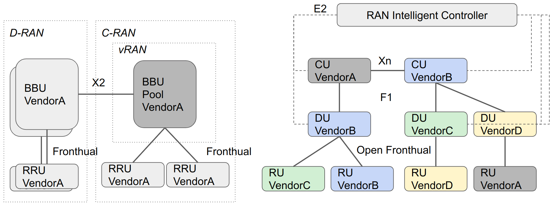
The D-RAN was based on the co-location of RRU and BBU at each cell site. All radio functions at every cell site are distributed, and connectivity to the core network is established through backhaul links, which are typically fiber optic cables. The D-RAN architecture is the term used to describe the traditional RAN architecture.
C-RAN (Centralized or cloud RAN)
C-RAN structure groups the BBUs from several sites into a pool located in one location, and the cell site only has the antenna and the RRU. This centralization of the BBU pool results in a new interface called fronthaul that enables multiplexing gains via interference cancellation and coordinated multipoint (CoMP) transmission. The fact that the BBUs use a hardware pool motivates the use of the term cloud for this RAN architecture. Do not confuse this with the cloud computing concept.
3GPP later improved this concept by defining the F1 split of the BBUs into the CU (Central Unit) and DU (Distributed Unit), where the protocol stack is split into two parts, as shown in the figure below. This split further enables the CoMP transmission and interference cancellation gains. Naturally, the CU is placed closer to the core network and the DUs are located closer to the cell sites, hence defining the fronthaul and midhaul interfaces. It should be noted that the gains of the F1 split are only viable if multiple DUs are connected to a single CU and the midhaul interface provides sufficient bandwidth.
V-RAN (virtual RAN)
V-RAN decouples the software from hardware by virtualizing Network Functions (NFs). The difference between V-RAN and C-RAN is that C-RAN uses the vendor's proprietary hardware and software while V-RAN uses virtualized proprietary software running on top of Commercial Off-The-Shelf (COTS) servers. This is how we are essentially able to run the lab software on the Google Cloud Platform (GCP) servers.
Open RAN
While V-RAN frees the operators from reliance on specific hardware vendors, the need for virtualization technologies for CU and DU from the same vendor persists due to proprietary software. Open RAN addresses this by introducing open interfaces in fronthaul, mid-haul and backhaul, allowing customers to mix components from different vendors for Open RAN networks.
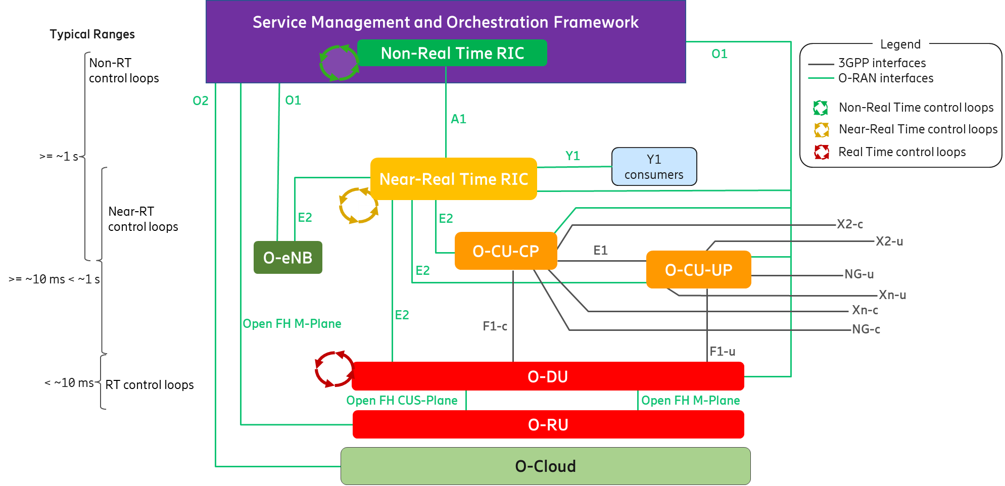
Based on the concept of Open RAN, the O-RAN Alliance was formed in 2018 by a group of operators to drive the adoption of open interfaces and virtualization of RAN components. The O-RAN architecture shown in the figure below is designed based on three principles:
- Open interfaces for multi-vendor interoperability
- Intelligent RAN control
- Virtualization of NFs
